Measure the flight path
High-speed video tracks the ball through successive frames. Camera calibration converts image positions into a 3D flight path. The resulting measurements help estimate launch speed and angle for the physical model.
The model starts with a trajectory that ignores air resistance, then calculates corrections for conditions that this simple trajectory does not represent.
Simulate drag and spin
Offline simulations account for aerodynamic drag, the force caused by ball spin (the Magnus effect), and energy losses in the mechanism. They calculate the changes needed in horizontal and vertical launch velocity.
The manual reports about 534 million underlying simulation calculations across parameter combinations. This is a simulation count, not a count of physical test shots.
Calculate settings on the robot
The simulation results are approximated with fifth-order polynomials using horizontal distance and the highest point of the flight path, called the apex. Evaluating these polynomials is less computationally expensive than running the full simulation during every control cycle.
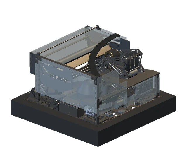
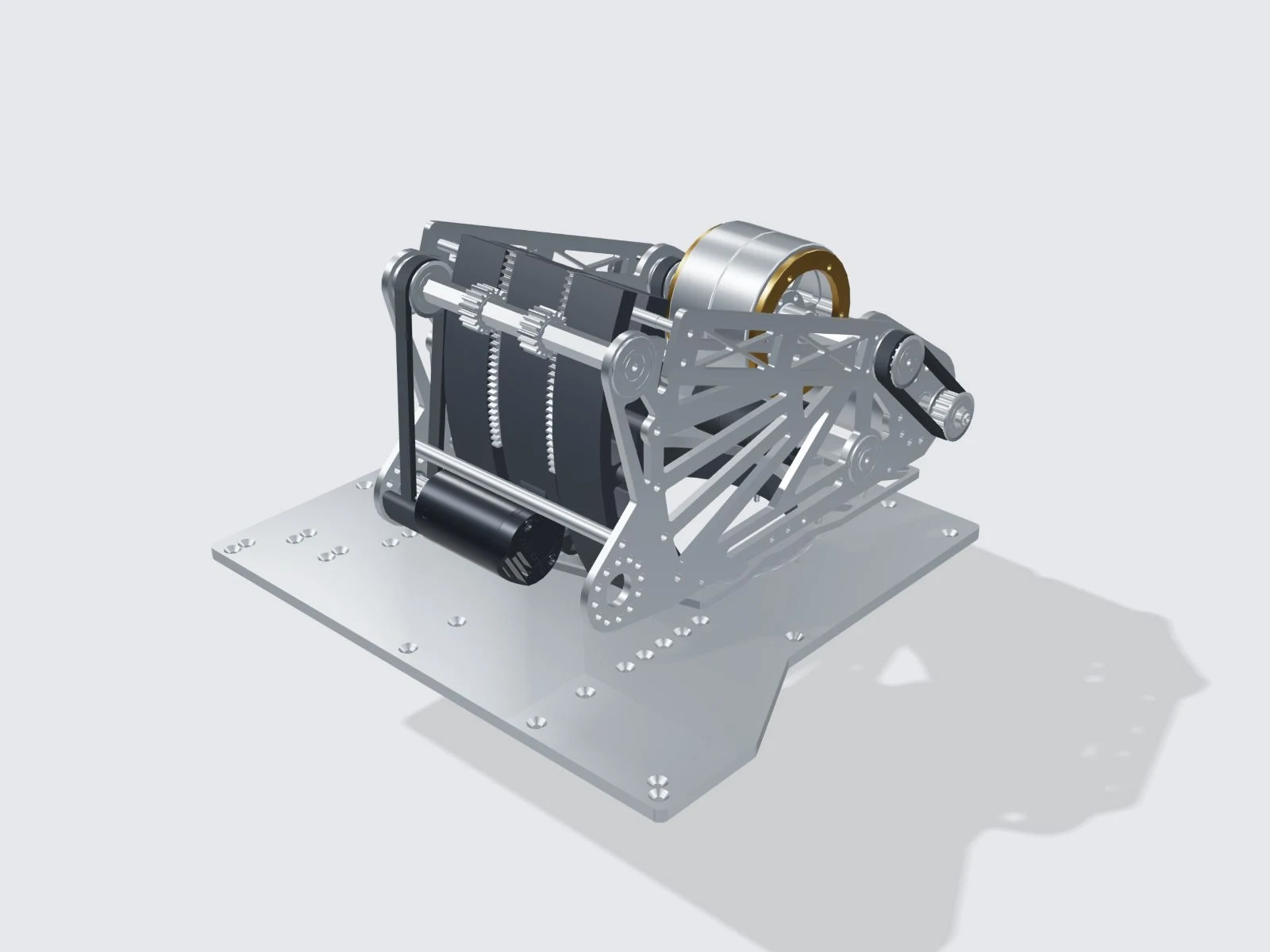
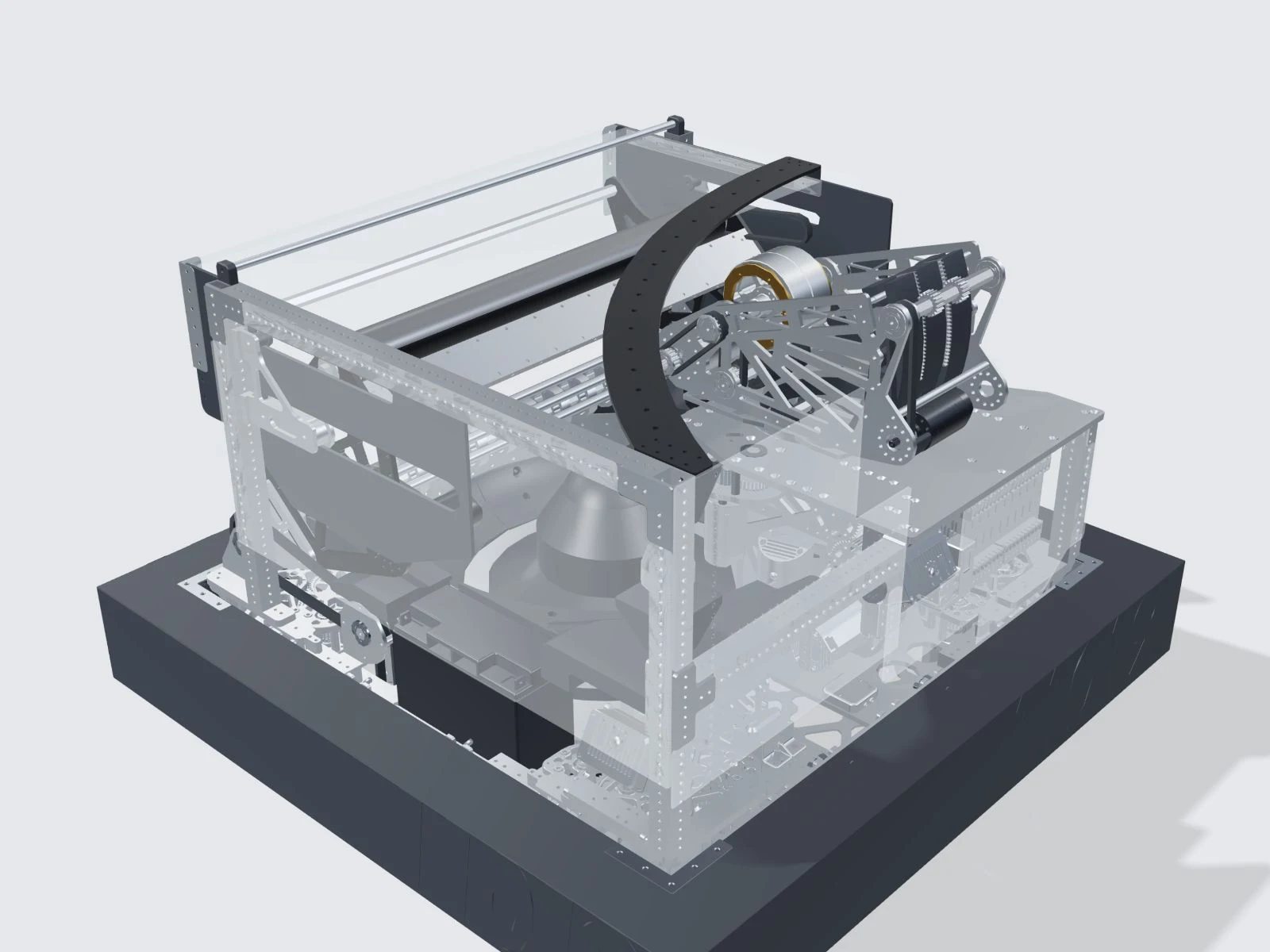
The robot then calculates flight time, accounts for chassis movement, and sets turret, hood and flywheel targets. Field accuracy still depends on calibration and how closely operating conditions match the model.