Launch speed and angle
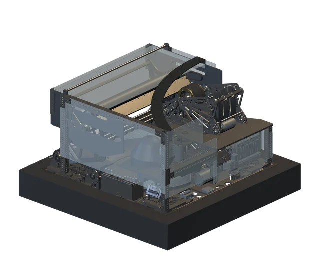
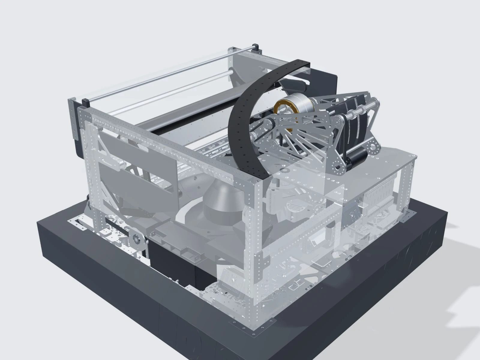
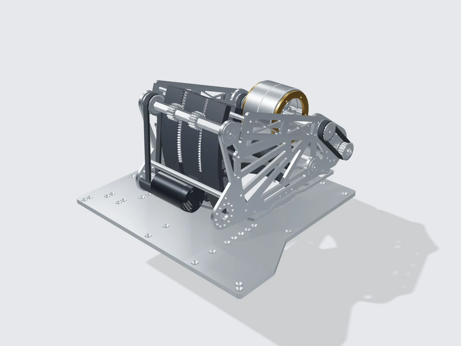
Two Kraken X60 motors drive metal-core, 50A polyurethane flywheels through a 1:1 ratio. The flywheels accelerate the ball as it passes through the shooter.
The hood guides the ball’s exit angle. The March manual specifies 25 degrees of hood adjustment and a PLA-CF backplate. Hood position and flywheel speed are adjusted together to produce the required flight path.
Independent aiming
A Kraken X44 drives the turret through a 126-tooth pulley. The manual specifies 360-degree rotation, allowing the shooter to point in a different direction from the chassis.
On this website, pointer tracking rotates the upper shooter assembly while the fixed mounting plate stays with the chassis. This helps show which parts move together; it is not a validated simulation of the robot’s operating limits.
Coordinated control
The control system calculates target values, or setpoints, for turret angle, hood position and flywheel speed. Adjusting direction alone is not enough when distance or robot speed changes.
A ball also carries the robot’s velocity when it leaves the shooter. The moving-shot calculation accounts for that contribution before setting the shooter’s targets.