← Team 11019

XPLORE 11019 · FRC ROBOTICS · 2026

Celestial Pivot.

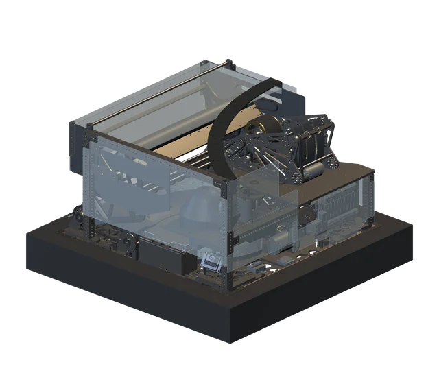
Material-rendered full robot from the supplied STEP model
XPLORE 11019ENGINEERING / 3D

Complete robot

Opening the 3D viewer

Checking for a saved copy of the model.

MODEL PREPARATION
  1. 01Load
  2. 02Prepare
  3. 03Render

Complete robot. Opening the 3D viewer.

Omnidirectional drive.
Independent turret.
Motion-compensated shooting.

01 — COORDINATED MOTION

Drive direction.
Launch direction.
Independent.

Four steerable wheels move the robot. The turret aims independently, while the hood and flywheels control the launch angle and ball speed.

SCROLL TO EXAMINE THE ASSEMBLY
02 — ASSEMBLY ARCHITECTURE

Inside the
machine.

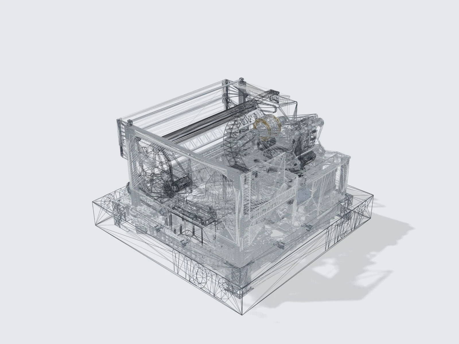
Collection, indexing and launch mechanisms arranged within one compact chassis. Explore the supplied assembly geometry, from the complete robot to individual systems.

ILLUSTRATIVE SEPARATION · NOT A DISASSEMBLY PROCEDURE

Discover the systems ↓
↓Scroll to explore
THE MACHINE / 2026
REAL STEP GEOMETRY
Illustrative material finishes
01
03

01 / MECHANICAL SYSTEMS

Three systems.
One platform.

Explore how the intake collects FUEL, the turret aims the shooter and the four steerable wheels move the robot.

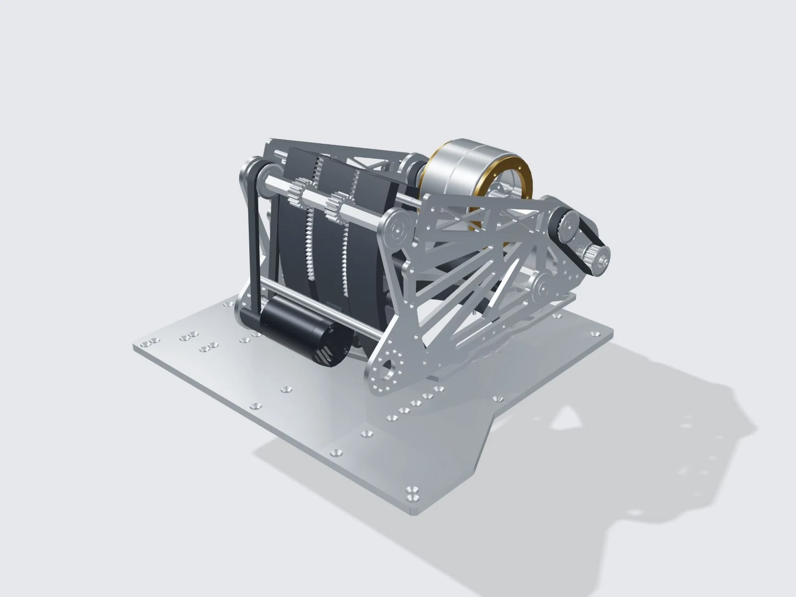
Material-rendered Turret & shooter from the supplied STEP
01 / ASSEMBLY STUDY
360°Turret rotation · March manual

Independent control of aim, angle and speed.

The turret sets aiming direction, the hood sets launch angle, and the flywheels set ball speed. The turret can turn independently of the chassis.

The March manual specifies 360° turret rotation and a 25° hood adjustment range. The current STEP preserves the assembly geometry; it does not include joint limits or motion constraints.
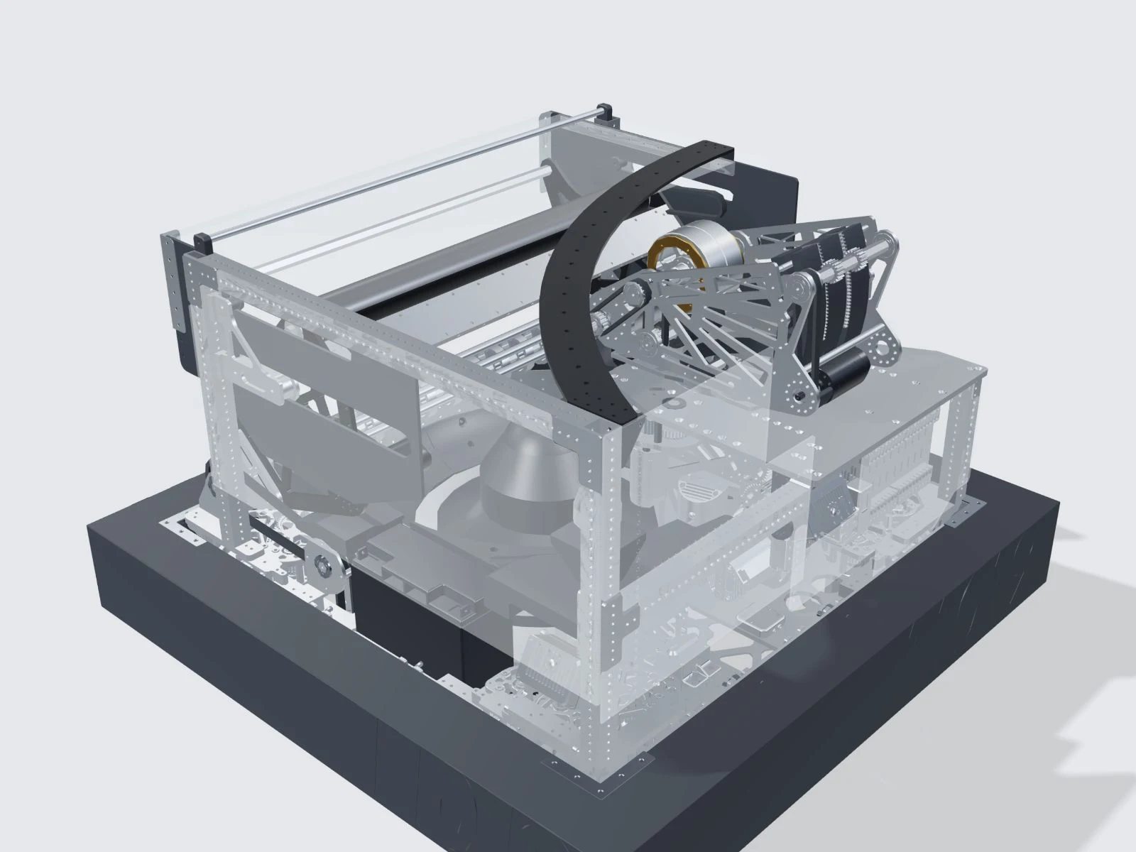
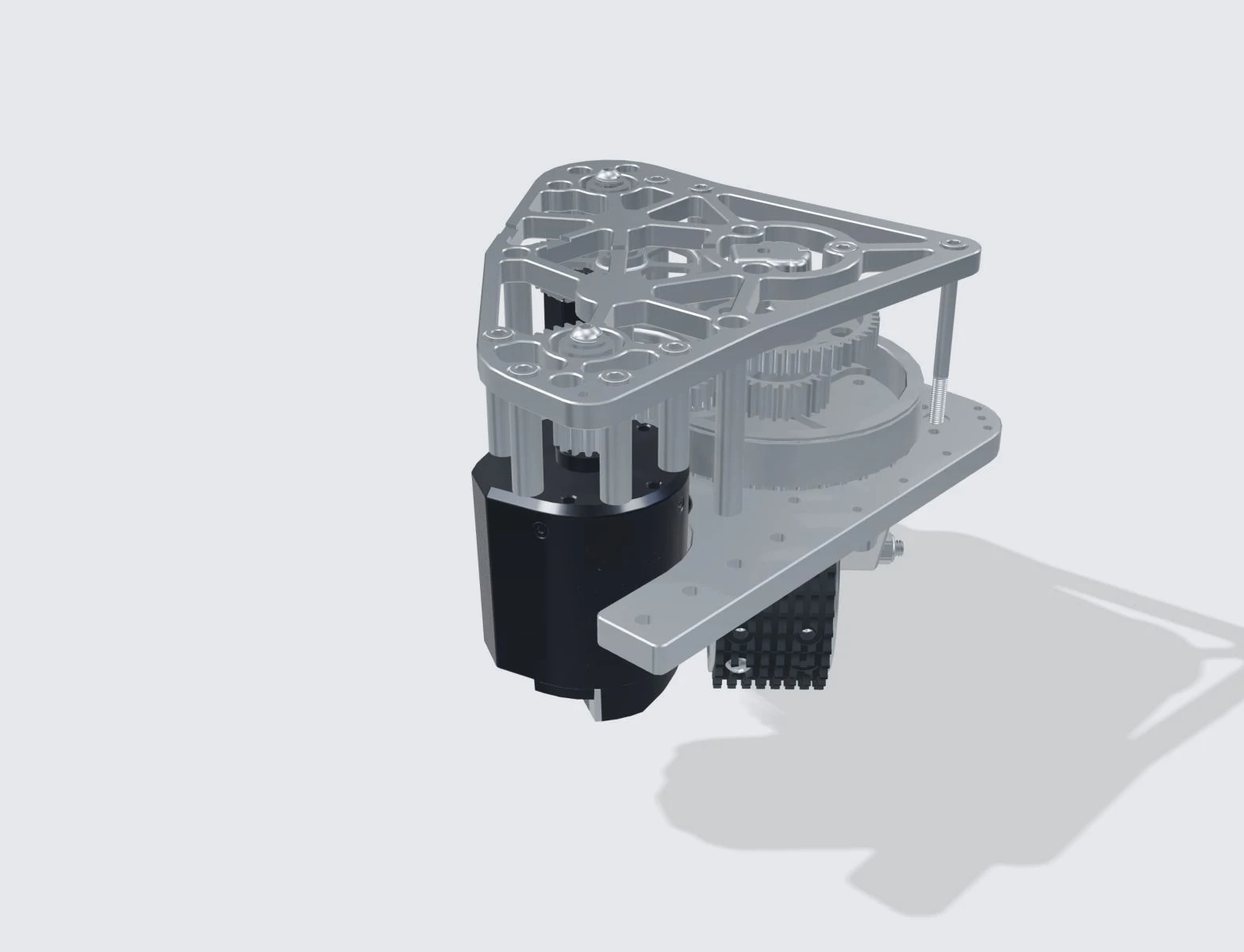
From floor intake to shooter.

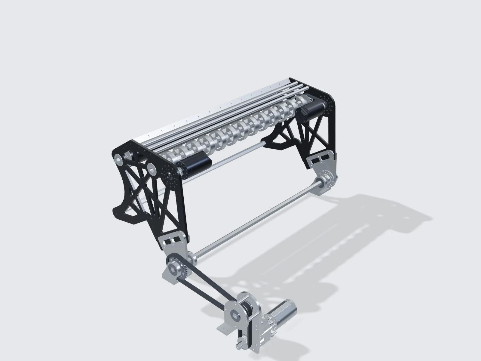
Front rollers transfer FUEL into the storage and feed path. A carbon-fiber tube supports the intake across the front of the machine.

The manual identifies a 35 mm carbon-fiber tube and two Kraken X44 motors. This standalone STEP shows a different intake configuration from the complete robot export.

Drive and turn independently.

Each of the four wheels controls its speed and steering angle. Together, they let the robot move sideways, turn, or do both at once.

The supplied module CAD is labeled MK2r; the March technical manual describes MK5R. These revisions are documented separately, not treated as identical hardware.

02 / CONTROL ENGINEERING

Shot calculation.
Motion and control.

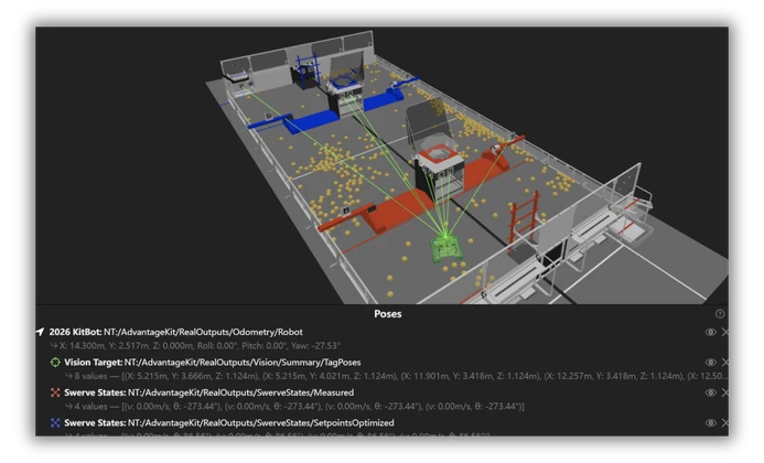
The control system calculates shooter settings, accounts for robot movement and corrects camera delay. Explore each function with the demonstrations below.

03 / SHOOT-ON-THE-MOVEVISTAeroSpin-5D

Shoot on the move.
Velocity compensation.

Calculate flight time from the current trajectory.
Subtract chassis translation from the required field-relative launch velocity.

v_launch/robot = v_required/field − v_chassis/field
READY TO FIRE01 / SHOOT-ON-THE-MOVE
Draggable Celestial Pivot robot, rendered from current STEP
00HITS / 00 SHOTS
6.14METERS TO TARGET
VELOCITY COMPENSATION

Motion compensation

← −3.00+3.0 →
Idealized demonstration · not a prediction of robot performanceDrag / Arrow keys to move · Space to fire
A MATCH IN MOTION0:36
TELEOPTeleop includes alternating shifts. Schedule collection and shooting around the active HUB windows.
0:00 / AUTO0:20 / TELEOP2:10 / END GAME2:40
MARCH 2026 / DOCUMENTED DESIGN

Robot
specifications.

Specifications below belong to the March technical manual. The September CAD remains a separate geometry release.

Drive
Four-module MK5R swerve
Specified maximum speed
4.58 m/s
Hopper travel
260 mm
Intake
Dual 35 mm carbon-tube rollers
Turret rotation
360°
Hood adjustment
25°
Vision
Two independent Limelights
Trajectory model
VISTAeroSpin-5D
THE 2026 ENGINEERING NOTEBOOK

Robot design, explained.

Download the complete manual
01

Robot systems

How the drivetrain, intake, hopper, feeder and shooter work together.

↗
02

Swerve drive

Each wheel controls its speed and steering angle. The robot can move sideways, turn, or combine both movements.

↗
03

Intake and feeding

Rollers collect FUEL from the floor. The hopper stores it, and the feeder delivers it to the shooter.

↗
04

Turret and shooter

The turret controls aiming direction, the hood controls launch angle, and the flywheels control ball speed.

↗
05

Shot calculation

VISTAeroSpin-5D uses detailed offline simulations to produce a smaller calculation that can run on the robot.

↗
06

Shooting while moving

The robot’s movement changes the ball’s launch velocity. The aiming calculation accounts for that added motion.

↗
07

Camera latency correction

Camera images arrive after capture. The system corrects the earlier position estimate, then updates it using the robot’s recorded movement.

↗
08

Autonomous control

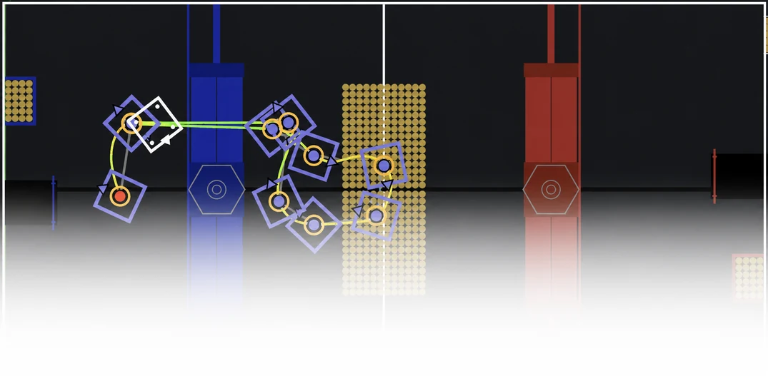
Follow a planned route while coordinating intake, feeding and shooting.

↗
09

Interactive CAD model

Inspect the complete robot or an individual assembly. Rotate the model to see how the parts fit together.

↗

03 / THE FIELD RECORD

Engineering.
In the field.

The team’s own photographs.
The machine beyond the CAD model.

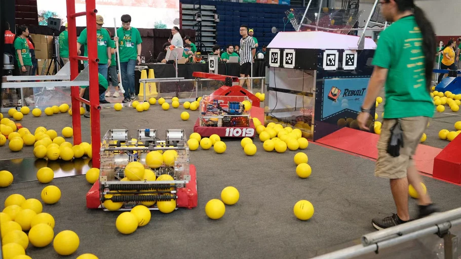
On the competition floor
01 / 04

On the competition floor

Event operation, documented in the March technical manual.

March 2026 photographs document an earlier revision than the supplied September CAD.

Preparing robot models: 0 of 4 ready.