A connected route through the robot
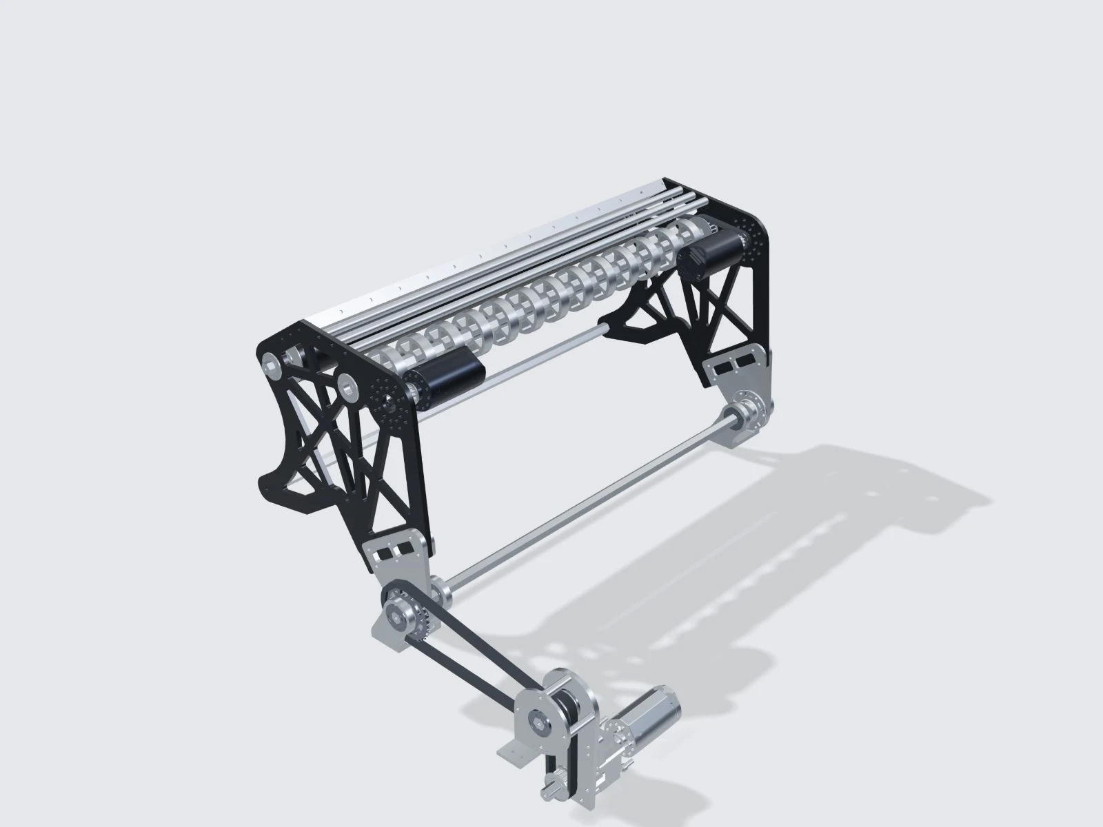
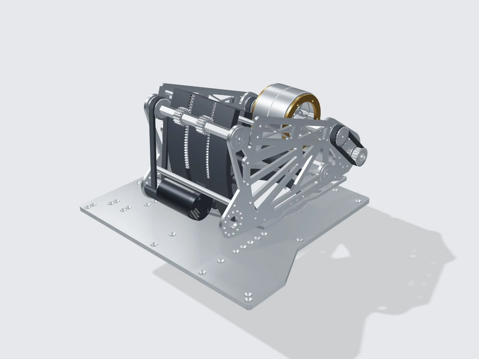
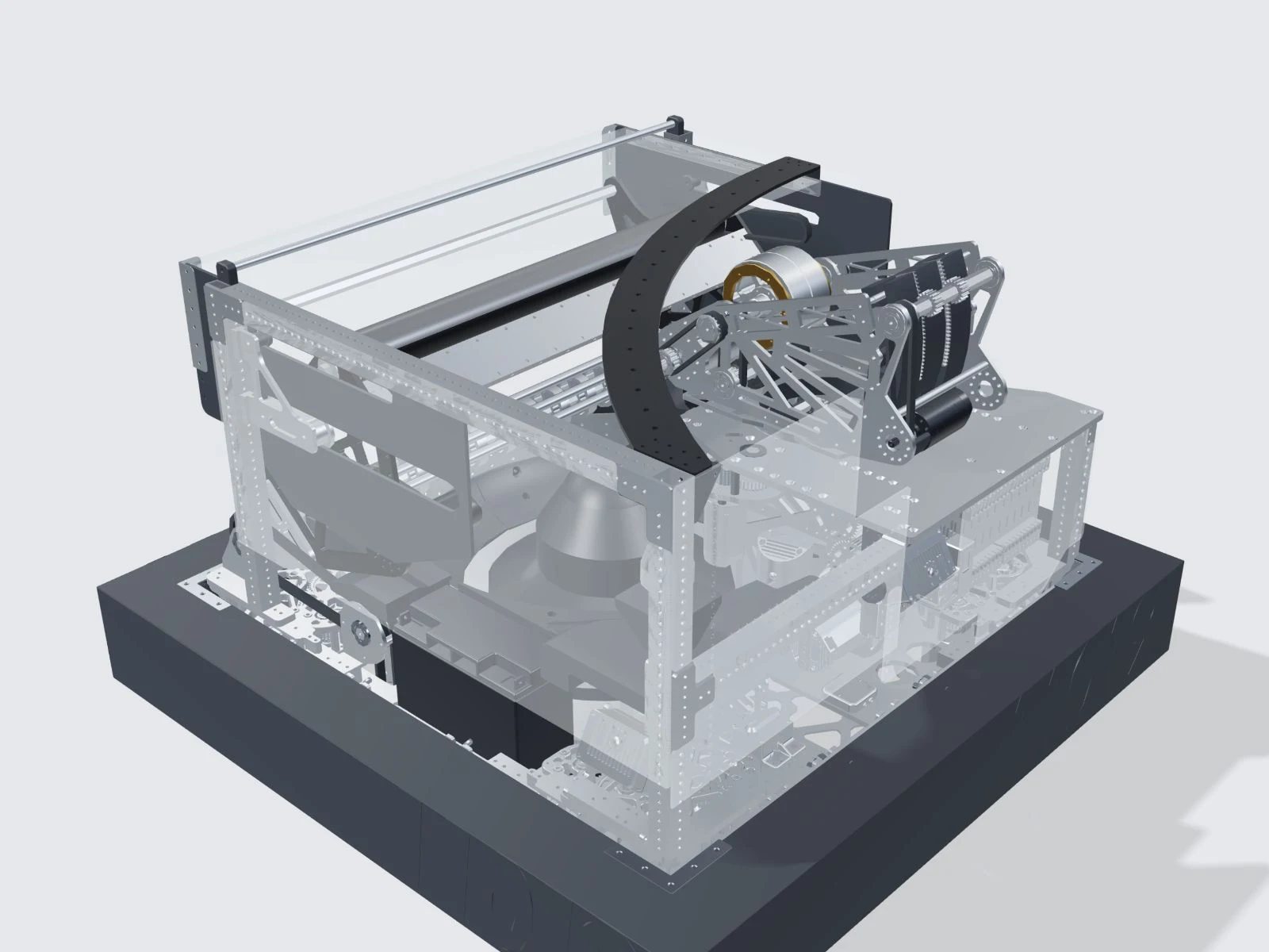
The front intake collects FUEL, the game’s foam balls. The hopper stores them, the feeder delivers them to the shooter, and the turret aims the shot. Each mechanism must pass the ball to the next without blocking the route.
The layout affects how well these parts work together. The intake must line up with the hopper entrance, the feeder must reach the stored balls, and the turret needs clearance to rotate. A fast intake is useful only if the rest of the robot can handle its output.
Structure and assembly
The March manual describes carbon-fiber tubes, machined aluminum, dual-bearing supports and locating flanges. These components support the mechanisms and keep shafts and assemblies aligned. The CAD model shows how they fit within the chassis.
The March manual and September CAD describe different revisions. Use the manual for the stated specifications and the CAD to inspect the supplied geometry.
Sensors and control
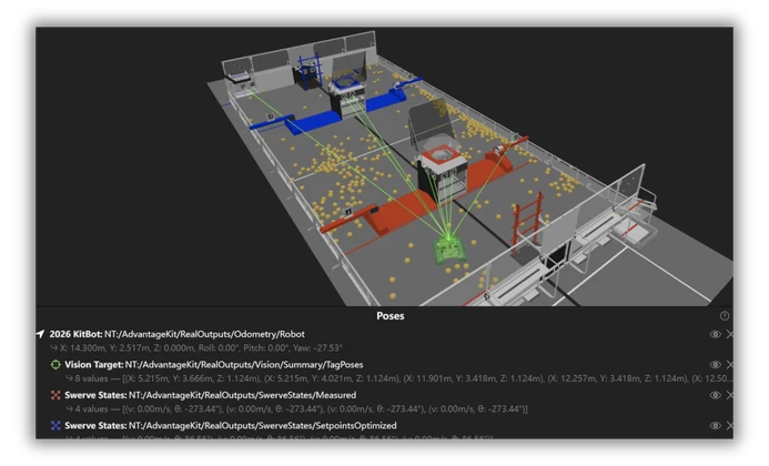
Wheel sensors and a gyro track the robot’s position and heading. Cameras provide additional position measurements. The shooting calculation uses this information to set the turret angle, hood position and flywheel speed.
During autonomous operation, software coordinates driving, collection and shooting. The mechanical and control chapters explain these connections in more detail.